|
CLASS |
FLUID |
MATERIAL |
RATING |
CONDITIONS |
VALVE TRIM |
ALLOWABLE |
|||||
|---|---|---|---|---|---|---|---|---|---|---|---|
|
kgf/cm2 |
psig |
|
deg C |
deg F |
||||||
|
A1 |
Liquid and |
C.S. ASTM A53 Gr.B |
150# |
Máx |
20.0 |
285 |
Mín |
38 |
100 |
Trim # 5 |
1.5 mm |
|
Mín |
5.6 |
80 |
Máx |
427 |
800 |
||||||
|
A2 |
Demineralized Water, |
C.S. ASTM A53 Gr.B |
150# |
Máx |
20.0 |
285 |
Mín |
38 |
100 |
Trim # 8 |
3.0 mm |
|
Mín |
18.3 |
260 |
Máx |
93 |
200 |
||||||
|
A3 |
Instrument Air |
GALV. C.S. A53 Gr. B |
150# |
Máx |
10,5 |
150 |
Mín |
25 |
77 |
Trim # 8 |
0.0 mm |
|
Mín |
7 |
100 |
Máx |
54 |
130 |
||||||
|
B1 |
Liquid and Gaseous |
C.S. ASTM A53 Gr.B |
300# |
Máx |
52.0 |
740 |
Mín |
38 |
100 |
Trim # 5 |
3.0 mm |
|
Mín |
38.6 |
549 |
Máx |
318 |
604 |
||||||
|
B2 |
LPG |
KCS ASTM A106 Gr.B |
150# |
Máx |
52.0 |
740 |
Mín |
38 |
100 |
Trim # 5 |
1.5 mm |
|
Mín |
38.6 |
549 |
Máx |
318 |
604 |
||||||
|
C1 |
Liquid and Gaseous |
C.S. ASTM A53 Gr.B |
600# |
Máx |
104 |
1480 |
Mín |
38 |
100 |
Trim # 5 |
3.0 mm |
|
Mín |
46 |
654 |
Máx |
443 |
829 |
||||||
|
E1 |
High pressure |
A.S. |
1500# RJ |
Máx |
263.7 |
3750 |
Mín |
38 |
100 |
Trim # 5 |
1.5 mm |
|
Mín |
37 |
526 |
Máx |
607 |
1125 |
||||||
The best thing to do in a real project is to copy from this
set of classes those classes that are nearest to the required classes and modify them
as required.
In our case, we'll copy the A1 class and leave it as it is. We have to run the EPLANT-Piping
Data Base module and open the example project. We selected then the following option:
 EPLANT-Piping Tutorial: Copy a Piping Class from Another Table (43sec)
A1 CLASS IN EPLANT FORMAT
To browse the class definition the following option is used:
A table made of vertical columns (fields) and horizontal rows (records) appears.
Each record corresponds to a component in the class. Each field represents an assigned
parameter to that component, in the specified diameter range.
Below you can see some of the components of the A1 class in EPLANT format.
|
CLASS |
COD |
OPE |
D1A |
D1B |
D2A |
D2B |
RAT |
SCH |
E1 |
E2 |
MAT |
CODA |
|---|---|---|---|---|---|---|---|---|---|---|---|---|
|
A1 |
45E |
1/2" |
1 1/2" |
3000 |
SW |
CM1 |
|
|||||
|
A1 |
45E |
2" |
2" |
XS |
BW |
CP1 |
|
|||||
|
A1 |
45E |
3" |
6" |
STD |
BW |
CP1 |
|
|||||
|
A1 |
45E |
8" |
12" |
20 |
BW |
CP1 |
|
|||||
|
A1 |
45E |
14" |
18" |
10 |
BW |
CP1 |
|
|||||
|
A1 |
45E |
20" |
24" |
STD |
BW |
CP1 |
|
|||||
|
A1 |
90B |
1/2" |
1 1/2" |
3000 |
SW |
CM1 |
|
|||||
|
A1 |
90B |
2" |
2" |
XS |
BW |
CP1 |
|
|||||
|
A1 |
90E |
3" |
6" |
STD |
BW |
CP1 |
|
|||||
|
A1 |
90E |
8" |
12" |
20 |
BW |
CP1 |
|
|||||
|
A1 |
90E |
14" |
18" |
10 |
BW |
CP1 |
|
|||||
|
A1 |
90E |
20" |
24" |
STD |
BW |
CP1 |
|
|||||
|
A1 |
BLI |
1/2" |
24" |
150 |
RF |
CM1 |
BLI02 |
|||||
|
A1 |
CAP |
1/2" |
1 1/2" |
3000 |
SW |
CM1 |
|
|||||
|
A1 |
CAP |
2" |
2" |
XS |
BW |
CP1 |
|
|||||
|
A1 |
CAP |
3" |
6" |
STD |
BW |
CP1 |
|
|||||
|
A1 |
CAP |
8" |
12" |
20 |
BW |
CP1 |
|
|||||
|
A1 |
CAP |
14" |
18" |
10 |
BW |
CP1 |
|
|||||
|
A1 |
CAP |
20" |
24" |
STD |
BW |
CP1 |
|
|||||
|
A1 |
CAP1 |
1/2" |
1 1/2" |
3000 |
SC |
CM1 |
|
|||||
|
A1 |
CHE |
1/2" |
1 1/2" |
800 |
SW |
CHE01 |
||||||
|
A1 |
CHE |
2" |
24" |
150 |
RF |
CHE02 |
||||||
|
A1 |
CPL |
1/2" |
1 1/2" |
3000 |
SW |
CM1 |
|
FIELD DESCRIPTION
Three codes are used: COD, MAT and CODA. All other parameters contain the value of the corresponding parameter. Below you can see the use of the main fields:
|
FIELD |
DESCRIPTION |
|
PCLA |
Piping Class, up to nine characters long. |
|
COD |
Generic Piping Component Code. The first three characters are validated against the COD field in the system table \PD\STD\COD.DBF. Longer codes can be used, for example CRE1. This allows to assign different parameters to the same component in the same diameter range. This possibility is compatible with the naming rules used by dimensional tables, which only use the first three characters. |
|
OPE |
It is used only for valves: it is the operator code associated to the valve defined in the COD field. If this field is left void, the valve will be generated without operator. The operator can also be added later or removed at any time, being a separate component. Additonal characters, if any, are used in the creation of the names used in dimensional tables only, whose names begin with the content of this OPE field followed by the parameter number and the end codes if required. |
|
D1A |
Lower Main Diameter Range, in inches. It is checked during input with the field DIAM in the \PD\STD\ANSI\PIP.DBF table, for the Ansi standard. |
|
D1B |
Upper Main Diameter Range, in inches. It is checked as D1A. |
|
D2A |
Lower Secundary Diameter Range, in inches. Required only for reductions. It is checked as D1A. |
|
D2B |
Upper Secundary Diameter Range, in inches. Required only for reductions. It is checked as D1A. |
|
RAT |
Rating of the main diameter, up to four characters. The allowed schedule values are listed in the \PD\STD\RAT.DBF table. |
|
SCH |
Schedule of the main diameter, up to six characters. It can be used also for thickness. The allowed schedule values are listed in the \PD\STD\SCH.DBF table. |
|
E1 |
End Code for the connection points 1 and 3. The allowed values are listed in \PD\STD\END.DBF table. This code is used also to define the name of the dimensional and weight tables of the component. The position of the connection points changes with the component type. |
|
E2 |
End Code for the connection points 2 and 4. Idem as above. If this field is not specified, the system assumes it equal to E1. |
|
MAT |
Material Code. It is validated with the MAT field in the \PD\STD\MAT.DBF table. If the material code put in the class is not defined in the material table, no material description will appear for it. Some commands will warn the error, typically the isometric MTO. |
|
CODA |
Additional Code. It is checked against the CODA field in the [project_code]CD.DBF table. If this code is defined in this table and has a text associated to it in the Memo field, this text will appear in material reports. This code has two main functions: to enable to complete the description associated to the generic component code(\PD\STD\COD.DBF table) and to associate an arbitrarily long text (it is stored in a Memo field, it can be any longer) to be used in the Material Requirement descriptions. Depending of the project setup, this table can also be the system \PD\STD\PIPCD.DBF table. |
|
THCK |
Gasket Thickness / Component Dimension for those components that have enabled the reading of a dimensional parameter from the piping specifications, such as Nipples. |
The D2A and D2B fields must be left void, unless for reductions, olets, relief valves, that is, piping components that have different diameters.
The following fields are less used, but they are very important because allow to setup very special cases:
|
FIELD |
DESCRIPTION |
|
RAT2 |
Rating of Secundary Diameter, up to four characters long. |
|
SCH2 |
Schedule of Secundary Diameter, up to six characters long. |
|
STU |
If this field is left blank and the component has flanged ends that generate implicit elements, a set of Studs is generated with the STU code. This code must be defined in the class to be able to associate a material to Studs. To generate another code, for example BLT (machine bolts) this code must be put in the STU field. Also in this case, the BLT code must be present in the class to assign material. |
|
GAS |
If this field is left blank and the component has flanged ends that generate implicit elements, a gasket will be automatically generated with the default code GAS. This code must be defined in the class to be able to associate a material to Gaskets. To be able to generate a different gasket code, this field must be filled with that code, for example GAS1. |
|
STD |
If this field is left blank (it is by far the most common case) the component will assume a dimensional standard as defined in the project setup. Any name put in this field is interpreted as the reference standard for that component. In this case a directory with that name must exist, nested in the \PD\STD directory. |
|
SPOOL |
Used to load the Spool code in case this option is enabled in the Project setup. |
ALTERNATED COMPONENTS
If in the same diameter range there is the necessity to use the same component
with different parameters, additional records can be added to the piping class, adding
an additional arbitrary character to the Generic Code.
For example, if we need a Gate Valve with the following options in the same diameter range
(from 1/2" to 1 1/2"):
- both ends socket welded
- one end BW and the other screwed
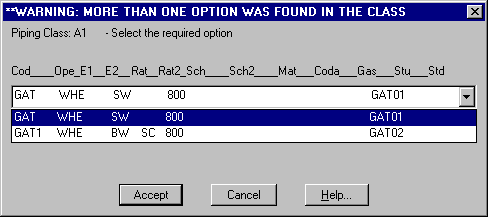
the GAT and GAT1 codes can be used, to assure that the code is unique, and
assign to these codes the required end options. During the placement of a Gate Valve
in that class in the diameter range from 1/2" to 1 1/2", the following window will
automatically appear:
Which allows selecting the option required for that specific case.
CLASS COPY, DELETE AND RENAME
The Copy option has been already explained before. There are other options to copy, delete and rename a piping class within the current project:
FITTINGS/FLANGES GENERATION
Fittings and Flanges can also be added to a class with this option, which allows selecting Fittings and Flanges from a list and to automatically open each component with the same diameter range and Schedule values as pipe components have:
Selecting this option, the following window opens:
RECORD MODIFY, DELETE AND UNDELETE
To MODIFY a record, the field to modify is to be selected and modified.
 EPLANT-Piping Tutorial: Modify a Record in a Piping Class (42sec)
To ADD a new record you can use the menu option:
Browse / Append Record
 EPLANT-Piping Tutorial: Add a Record in a Piping Class (53sec)
To DELETE a record, mark the record to delete as shown in the animation:
 EPLANT-Piping Tutorial: Delete a Record in a Piping Class (40sec)
The record delete is a temporary action. Deleted records can be undeleted with the option:
To delete them permanently select Pack of the table option from the same menu.
PIPING SPECIFICATION CHECKING
Before using newly loaded Piping Classes it is advisable to carry out a complete verification of all of them looking for formal errors. The following option can be used:
Before to execution a Help button will explain in detail all the verifications that this command will enable.
DIMENSIONAL CATALOG VERIFICATION
This option allows to verify the Dimensional Catalog required by the project Piping Specifications. All dimensional tables required are verified looking for missing diameter ranges and null values. The following option is used:
INSULATION SPECIFICATIONS
EPLANT-Piping allows defining Insulation Classes. For each class the insulation thickness is defined to each possible nominal diameter. Select the option:
The table format is the following:
|
FIELD |
DESCRIPTION |
|
CLASS |
Insulation Class, any name up to six characters long. Identifies the insulation material. If this code is added as an Additional Code in the Additional Code table, then a full description can be loaded and will appear in the Material Requirements for the insulation material. |
|
DIAM |
Nominal Piping Diameter. No ranges admitted, only specific values. |
|
I_TH |
Insulation thickness corresponding to that diameter. Up to six characters long. |
|
I_MM |
Insulation thickness in mm. Used for interference checking only. |
|
MAT_INS |
Contains the Material Code associated to the insulation. |
|
CODA_INS |
Contains the Additional Code associated to the insulation. |
|
LINING |
Lining Code. If it is equal to 1, Insulation Lining will be generated with the same quantity as the insulation. |
|
MAT_LIN |
Contains the Material Code associated to the Insulation Lining. |
|
CODA_LIN |
Contains the Additional Code associated to the Insulation Lining. |
The insulation class is assigned to each component at the moment of its creation. It can be modified later also.
The insulation material is automatically generated during the Material Requirement generation.
CODES
EPLANT-piping works with a set of internal codes. To each one a table in DBF format corresponds. Those tables can be browsed and changed from the corresponding option in the Reference menu bar.
Generic Component Code (COD): it is the main identification code for components, assigns a short description and other basic parameters. One of the most important is the PDL code which is related to the 3D component shape.
Material Code (MAT): assigns a text with the description of the material.
Additional Piping Code (CODA): assigns an additional description to the description associated to Component and Materials codes and component parameters. It is used in the Material Requirements.
It has the following format:
|
FIELD |
DESCRIPTION |
|---|---|
|
ADDITIONAL CODE |
Additional Code, any name up to 16 characters long. It is very convenient to use a simple rule when creating a new code, for example using the firsts three characters equal to the COD code. |
|
DESCRIPTION |
With a double click on the memo word an editor window will display, allowing to input the required description. Closing this window, the written text is automatically saved. A memo field with text inside is signaled with the first capital letter Memo. |
|
SHORT DESCRIPTION |
To load a short description. It is useful when browsing data to suggest what each memo field might contain. |
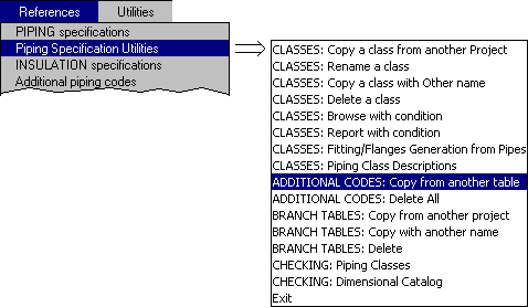
The Predefined Classes have theirs respective Additional Codes defined. These codes can be easily copied to the project with the option:
 EPLANT-Piping Tutorial: Copy Additional Codes from Another Table (52sec)
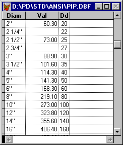
Diameters are checked against the PIP.DBF table that can be browsed from References / 3D Components Dimensions with the following content:
It has the following format:
|
FIELD |
DESCRIPTION |
|---|---|
|
DIAM |
It is the diameter, as it is loaded in the diameter fields in the specifications. |
|
VAL |
It is the external pipe diameter in mm. |
|
DD |
It is an internal code used for ordering and in the Requisition Grouping Criteria. |
REQUIRED FIELDS
Depending on the component type, some fields must be loaded and others must be left void. Below is a summary with the main rules, which are automatically enforced by the data base module.
- Main Diameter Range: must be specified for each component. They must be valid diameters.
- Pipes: Schedule or Thickness must be loaded in the SCH field. The end code in the E1 field can be left void to allow connecting with any other end code.
- Flanges: E1 field must be a flanged code, E2 field must be a non flanged one.
- Flanged Components: the Rating value must be specified in the RAT field.
- Components with only one connection point: they cannot have E2 code.
- Reduction Components: the Secundary Diameter Range must be specified.
- Material Code: can be left void and also an invalid code may be used, to be able to load it in the System Material Code table afterward. In this case a warning message is automatically issued.
- Additional Code: can be left void (this is the most common case) and also an invalid code may be used, to be able to load it in the Project Additional Codes table afterward. In this case a warning message is automatically issued.
EXCEL EXPORT / IMPORT
Although the data base module allows to create and modify in many ways any specification, it is possible
to export the Specifications and Branchs Tables from the internal DBF format to a CSV file. This format
is compatible with any version of Excel and other spreadsheet programs. Work with
Excel and then Import the CSV file inside EPLANT.
To avoid corrupting the DBF file avoid using the Export DBF to XLS. Use instead the command:

In case the Piping Specifications are to be exported, select the /[project]/DBF/[project]SP.DBF file:
In this way, a file with the same name as the source one, but with CSV extension is generated. This file can be edited with Excel. It must be saved with the same format. To import it in the original DBF file, execute:

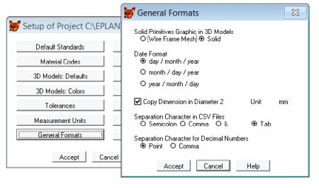
that prompts to select the CSV input file and the DBF file that will receive data. Only those fields with the same names in both files will be loaded in the DBF file. CSV files use a separation character to separate data into columns. In the Project Setup this character can be defined along with the decimal digits separation, that must be the same as the one defined by the operating system. This allows Excel to corretly identify numbers:
After an external manipulation of Specifications, always execute the command: CHECK Piping Classes to correct any possible formal errors: codes and diameters not defined, etc.
COMMODITY CODE MANAGEMENT
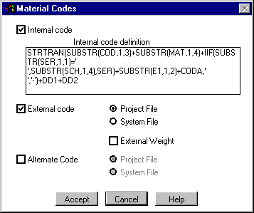
When the project requires the use of a Custom Commodity Code, the way to implenet this feature is by using the External Code. It has to be enabled in the project setup:
If the Commodity Code has less or equal to 16 characters, it could be possible simply to use the Additional Code for this purpose. But this would require identify each material specified in the Piping Classes with the corresponding Commodity Code and, in case that code includes the diameters, open up the definition of the Specification to each diameters instead of using diameters ranges. A better way is to use the External Code, that has the additional advantage to allow any lenght.
The main vantage is that the Commodity Code will only be needed to identify the material generated in the project, and not for all possible material specified in the Piping Specifications. To this aim, use the following option:
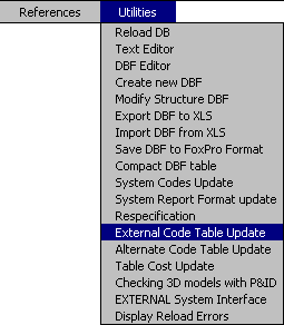
that opens the following window:
This command can be executed any time and again. The first option for Data Source, allows to update the table with the material currently in the project, loading the minimum possible data.
The External Code can be included in any material report, both in the data base and graphic module in isometric MTOs.
ADDITIONAL CODE GENERATION
In case the External Code is used, there is a feature to automatically generate the Additional Codes of the project for those materials that generally need it, tipically Valves and few other components to complete their descriptions. Following is the complete sequence to achieve that:
- Import User Defined Commodity Code into the Additional Code Table as External Code.
- Automatically generate Additional Codes from External Codes.
- Add theese Additional Codes in Piping Specifications when required.
- When required during project execution, update the External Code table: new entries will be identified by parameters specified in Piping Classes only.
- Using the correspondence between Additional Codes and External Codes in the Additional Code table, it is possible to automatically filling the External Code for those materials that make use of the Additional Codes. The rest of the materials must be filled manually.
Here the process in detail. We have to start with the User Defined Commodity Code defined in an Excel file, such as this one:
Next it is better to change the names in the first two columns, as to conform to EPLANT column names and to be able to easily copy whole columns:
To import External Code definition we need to generate a template of the Additional Code table in CSV format. Because the description text associated to External Code contains comas, we need to change the separator character. In this case we choose to use a Tab.
Now we generate the template of the the Additional Code table, that is still void:
We need to rename it from the CSV extension to the TXT extension to force Excel to ask for the separator character, otherwise it will use a coma, or whatever is specified in the Windows configuration:
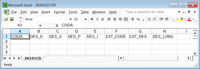
From Excel we use the Open command to open that TXT file. several configuration windows will open in sequence:
Up to the content of the file showing up. Columns must appear with their respective names in the first row, if this were not the case, the separation character in the template is not a Tag and the whole process must be repeated.
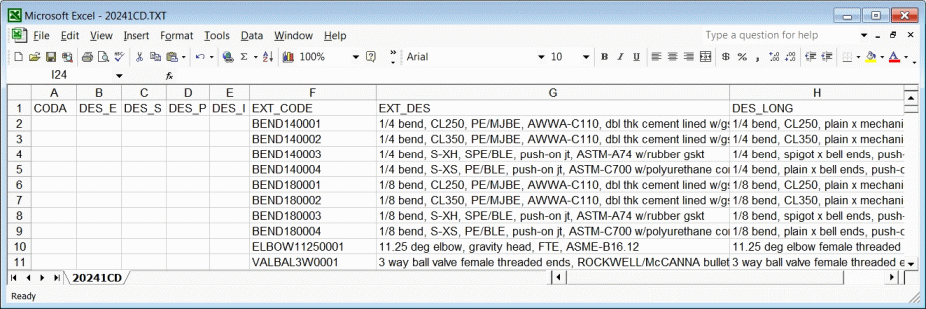
From the original table containing the commodity code values, we can copy the whole columns: EXT_CODE, EXT_DES and DES_LONG to our CSV (renamed TXT) file:
We are now ready to import back this CSV file into the corresponding DBF table of our project. No need to rename this file to CSV extension:
In this way we loaded the External Codes and their descriptions in the Additional Code definition table.
Now we can take advantage of this option in the UTILITIES menu to automatically generate Additional Codes: this command will take the first three characters of the corresponding External Code and adding to it a progressive number in a way to generate unique codes.
With Accept, the generation is executed.
This is the result with the Additional Codes generated. Most of them will not be used:
Piping Classes are now ready to be completed using the Additional Codes defined in that way, exclusivelly for materials that require a specific description, such as Gaskets:
At any moment during project execution, the Data Base module could be syncronized. This operation sends the material generated in the project 3D models to the Data Base module. If material reports need to be generated including the External Code, its table must be updated. This table is used to set a correspondence between the material definition generated by the system and the corresponding External Code defined by the user. To this aim it is advisable to select the easy option, that is to include only the material generated for the project so far.
This is the result. This command only create the definition of materials generated by EPLANT based on Piping Specifications.
The External Code must be manually loaded, indentifying the associated description. But for those materials that use the Additional Code, the External Code could be automatically generated with:
This is the result where we can see External Codes loaded where the Additional Codes are specified:
Last Updated May 06th, 2025.


